
How to Extend Tool Life in Stainless Steel Machining
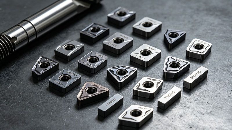
Stainless steel has a reputation as a difficult material, and the reputation is deserved — but not for the reason most operators assume. Stainless steel is not particularly hard. What makes it punishing is a combination of three behaviours that reinforce each other, and unless all three are addressed, tool life improvements made in one area are cancelled by the others.
The Three Mechanisms That Kill Stainless Steel Tooling
1. Work Hardening
Austenitic stainless steels (grades 304, 316, 316L and similar) harden rapidly under deformation. The cut surface can reach 1.5 to 2 times the bulk hardness immediately after a pass. Because the next pass cuts that hardened surface, each successive pass removes a harder layer than the last.
The consequence is an implicit requirement: the cutting edge must cut cleanly beneath the hardened layer in a single pass, never rubbing. Any rubbing action hardens the surface further, making the next pass worse. This creates a self-reinforcing failure loop that explains why stainless steel tool life can collapse suddenly rather than degrading gradually.
2. Built-Up Edge
Stainless steel is gummy and tends to weld to the cutting edge under pressure and heat. A built-up edge forms, grows, becomes unstable, then breaks away — taking a fragment of the coating or substrate with it. This cycle repeats many times per second, producing progressive edge degradation that looks like chipping or flaking rather than normal wear.
Built-up edge also degrades surface finish directly, leaving a torn or smeared appearance rather than a clean cut.
3. Concentrated Heat
Stainless steel has thermal conductivity roughly one third that of carbon steel. Heat generated at the cut is not conducted away into the chip or the workpiece efficiently, so it concentrates in a narrow zone at the cutting edge. This accelerates diffusion wear and, at higher speeds, softening of the edge itself.
These three mechanisms are linked: built-up edge generates friction and heat, heat accelerates work hardening through deformation, and work hardening increases cutting forces, which increases built-up edge. Breaking the loop requires addressing the process as a system, not adjusting one parameter.
Grade and Substrate Selection
Stainless steel sits in ISO group M and demands a substrate that balances toughness with hot hardness. Practical guidance:
- Cobalt content in the 8–11% range. Higher than steel grades (P), because the edge must survive built-up edge detachment without fracturing.
- Medium grain size. Fine grains add hardness that is useful in cast iron and hardened steel, but the toughness penalty is not worth it here.
- Limited cubic carbide content. A small amount improves hot hardness, but excess TiC/TaC/NbC reduces toughness and promotes notch wear.
- Avoid grades optimised for steel. A hard CVD-coated steel grade is the single most common cause of poor stainless steel tool life — it survives the heat but chips under the built-up edge cycle.
Coating Choice: PVD Over CVD
For stainless steel machining, PVD coatings are generally the correct choice.
- PVD TiAlN is the workhorse. Deposited at 400–500 °C, it produces a thin, fine-grained layer with high compressive stress, which favours edge toughness and resistance to chipping under built-up edge.
- PVD AlTiN or AlCrN suits the more demanding end — duplex and super-duplex stainless, and high-alloy grades where cutting temperature is highest.
- CVD multilayer with alumina offers better abrasion resistance but its thick, brittle nature and the η-phase at the substrate interface make it prone to flaking under the adhesive conditions stainless steel creates.
A thin PVD coating also preserves edge sharpness better than a thick CVD layer, which matters because sharpness reduces built-up edge formation in the first place.
Geometry and Edge Preparation
- Use positive rake geometries. Positive rake reduces cutting forces and the tendency to work harden the surface, at the cost of a weaker edge — which the tougher substrate compensates for.
- Prefer a light hone over a heavy T-land. A 0.02–0.04 mm hone gives edge strength without the high cutting forces a heavy chamfer introduces.
- Keep the edge sharp. A dull edge rubs, and rubbing is what ruins stainless steel surfaces. Change inserts before flank wear reaches the point where rubbing begins.
- Choose a chip breaker designed for the feed range you actually use. A chip breaker working outside its designed window produces either stringy tangles or excessive edge load.
Cutting Parameters
Stainless steel has a narrow parameter window. Too slow and the edge rubs, hardening the surface; too fast and diffusion wear destroys the edge. Typical austenitic stainless ranges with coated carbide:
- Cutting speed: 100–160 m/min for continuous turning of 304/316. Duplex grades drop to 60–100 m/min.
- Feed rate: 0.15–0.25 mm/rev. Never below 0.10 mm/rev — a feed that is too light causes rubbing.
- Depth of cut: 1.0–2.5 mm. Keep depth of cut above the work-hardened layer depth from the previous pass; too shallow a pass cuts in hardened material.
The parameter rule specific to stainless steel: never let the tool rub. If any of the three parameters is set so low that the edge slides rather than cuts, work hardening begins and tool life drops sharply regardless of grade quality.
Coolant Strategy
Coolant is not optional in stainless steel machining. The objective is to cool the cutting edge, not the workpiece, because cooling the workpiece raises its hardness relative to the cut.
- Direct high-volume coolant at the cutting zone, not over the part generally. A flood aimed at the top of the workpiece does little for edge temperature.
- Use high-pressure coolant (70 bar or above) where available. It reaches the chip-tool interface and provides both cooling and chip evacuation, and significantly reduces built-up edge.
- Avoid intermittent coolant. Alternating hot and cold cycles thermally crack the edge. Either use coolant continuously or not at all.
- Consider through-tool coolant for drilling and deeper cuts, where flood coolant cannot reach the cutting zone at all.
Machine and Setup Factors
Stainless steel amplifies any rigidity deficiency. Before adjusting tooling, check the basic setup:
- Minimise tool overhang. Any deflection is magnified by the high cutting forces stainless generates.
- Check spindle and turret condition. A small amount of run-out causes uneven edge loading, which is fatal at the edge.
- Confirm workpiece support. Long unsupported sections will deflect and chatter, and chatter produces rapid chipping.
- Consider a lighter depth of cut with a more rigid setup rather than a deeper cut on a marginal machine.
Diagnostic Reference: What the Wear Tells You
- Chipping or flaking of the coating — built-up edge cycle is too aggressive. Reduce speed slightly, raise feed, or switch to a tougher PVD grade.
- Notch wear at the depth-of-cut line — classic stainless failure. Reduce depth of cut, or vary the depth between passes to distribute the notch.
- Crater wear on the rake face — cutting temperature too high for the coating. Reduce speed by 10–15% or move to an AlTiN coating.
- Plastic deformation of the edge — speed too high and substrate hot hardness insufficient. Reduce speed, or select a grade with higher hot hardness.
- Poor surface finish with no obvious wear — built-up edge smearing. Increase speed by 20%, check coolant delivery, and confirm the edge is genuinely sharp.
- Sudden total failure after good life — work-hardened layer being cut. Increase depth of cut so the pass clears the hardened zone.
Summary Checklist
- Select a group-M grade with 8–11% cobalt, not a steel grade.
- Use a PVD TiAlN or AlTiN coating, not CVD alumina.
- Use positive rake geometry with a light hone, and keep the edge sharp.
- Set speed in the narrow 100–160 m/min window for austenitic grades.
- Never feed below 0.10 mm/rev, and never let the tool rub.
- Direct high-pressure coolant straight at the cutting zone, continuously.
- Ensure maximum rigidity in tool, holder and workpiece.
- Read the wear mode to identify which mechanism is dominating.
Stainless steel rewards a disciplined process. The material gives no latitude for a rubbed edge, a light feed or an interrupted coolant supply — but when each of these is controlled, tool life in 304 or 316 can approach that of plain carbon steel.
If a stainless steel application is consuming inserts faster than expected, send us the material grade, hardness, machine details and current parameters. Our engineering team will review the grade, coating, geometry and coolant strategy together and recommend a specific combination for your process.